Industrial Control STM32F407VET6 Cortex M4 Development Board RS232 RS485 Dual CAN Ethernet USB Host
Order before 12.00PM
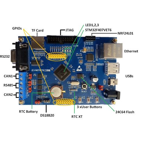
The development board uses the STM32F407VET6 chip as the main controller, M4 core, expansion with 1 RS232 interface, 1 RS485 interface, 2 CAN interfaces, 1 Ethernet port, 1 USB Host interface, 1 USB device interface, 3 User buttons, 3 indicators,. It's suitable for IoT application development, gateway server development, bus communication development and industrial control
Features:
- Core: ARM32-bit Cortex-M4 CPU with FPU, Adaptive real-time accelerator (ART Accelerator) allowing 0-wait state execution from Flash memory, frequency up to 168 MHz, memory protection unit, 210 DMIPS/1.25 DMIPS/MHz (Dhrystone 2.1), and DSP instructions
- Memories:Up to 1 Mbyte of Flash memory Up to 192+4 Kbytes of SRAM including 64-Kbyte of CCM (core coupled memory) data RAM Flexible static memory controller supporting Compact Flash, SRAM, PSRAM, NOR and NAND memories
- The development board adopts STM32F407VET6 chip as the main controller, M4 super core
- extended 1 channel RS232 interface, 1 channel RS485 interface, 2 channel CAN interface, 1 channel Ethernet interface, 1 USB HOST interface, 1 USB DEVICE interface , three user buttons, three user indicators.
- Ideal for IoT application development, gateway server development, bus communication development, and industrial control
Board Interfaces:
- CPU : STM32F407VET6-LQFP100
- Ethernet chip: DP83848-LQFP48
- Serial port: 1 RS232 interface with serial port 1 (PA9 PA10)
- RS485 interface: 1 RS485 interface with serial port 2 (PD5 PD6)
- CAN interface: 2 CAN interfaces with chip (PD0 PD1/ PB5 PB6)
- TF Card: 9-pin micro sd card, controlled by the PC and PD pins
- Wireless interface: P3 leads to NRF24L01 interface
- USB interface: One master USB and one slave USB
- Storage: Built-in 24C02 and 25Q64 memory chips
- Temperature sensor interface: Lead out DS18B20 sensor interface
- JTAG interface: JTAG corresponding to JLINK
- Buttons: K1, K2, K3 three user buttons
- Indicator light: LED1, LED2, LED3 user indicators
Pinout Details:
2.1. Power Supply Pins
- VDD: Core power supply (3.3V). Connect to a 3.3V regulated power source.
- VSS: Core ground. Connect to the ground of the power source.
- VDDA: Analog power supply (3.3V). Connect to the same 3.3V source as VDD.
- VSSA: Analog ground. Connect to ground.
- VREF+ / VREF-: Reference voltage for ADC. Typically connect VREF+ to a stable voltage reference (e.g., 3.3V) and VREF- to ground.
2.2. RS232 (USART1)
- TX (PA9): Transmit data pin.
- RX (PA10): Receive data pin.
- GND: Ground pin. Connect to the ground of the RS232 interface.
2.3. RS485 (USART2)
- TX (PA2): Transmit data pin.
- RX (PA3): Receive data pin.
- DE (PA1): Driver Enable pin. Used to control the direction of data flow in RS485 communication.
- RE (PA1): Receiver Enable pin. Connect to the same pin as DE for half-duplex operation.
- GND: Ground pin. Connect to the ground of the RS485 interface.
2.4. CAN (Controller Area Network)
-
CAN1:
- CAN1_H (PB9): CAN High pin.
- CAN1_L (PB8): CAN Low pin.
- GND: Ground pin.
-
CAN2:
- CAN2_H (PD1): CAN High pin.
- CAN2_L (PD0): CAN Low pin.
- GND: Ground pin.
2.5. Ethernet
- ETH:
- ETH_TX+ (PA1): Ethernet Transmit Positive pin.
- ETH_TX- (PA2): Ethernet Transmit Negative pin.
- ETH_RX+ (PA7): Ethernet Receive Positive pin.
- ETH_RX- (PA6): Ethernet Receive Negative pin.
- ETH_CLK (PC10): Ethernet Clock pin.
- ETH_MDC (PC1): Management Data Clock pin.
- ETH_MDIO (PC2): Management Data Input/Output pin.
- ETH_RST (PF0): Ethernet Reset pin.
- GND: Ground pin.
2.6. USB Host
- USB:
- VBUS (PA9): USB power supply pin.
- D+ (PA12): USB Data Positive pin.
- D- (PA11): USB Data Negative pin.
- GND: Ground pin.
Additional Pin Functions
- GPIO Pins: General-purpose input/output pins available on various ports (PA, PB, PC, PD, PE, PF, PG). These pins can be configured for various digital I/O tasks and alternate functions such as timers, ADC, DAC, and communication interfaces.
- Analog Inputs: Pins connected to the ADC (Analog-to-Digital Converter) for measuring analog signals.
- PWM Outputs: Pins capable of generating Pulse Width Modulated signals for motor control or other applications.
- Timers: Various timer pins used for generating precise timing signals or controlling external devices.
Example Applications
- RS232: Serial communication with external devices such as sensors or other microcontrollers.
- RS485: Communication over long distances or in noisy environments where differential signaling is needed.
- CAN: Automotive or industrial network communication for robust and reliable data transfer.
- Ethernet: Networking for industrial applications, remote monitoring, or data exchange.
- USB Host: Connecting USB peripherals like keyboards, mice, or storage devices.
Development and Programming
- STM32CubeMX: Use this tool for configuring peripherals, generating initialization code, and managing the microcontroller's settings.
- STM32CubeIDE: Integrated development environment for writing, compiling, and debugging code.
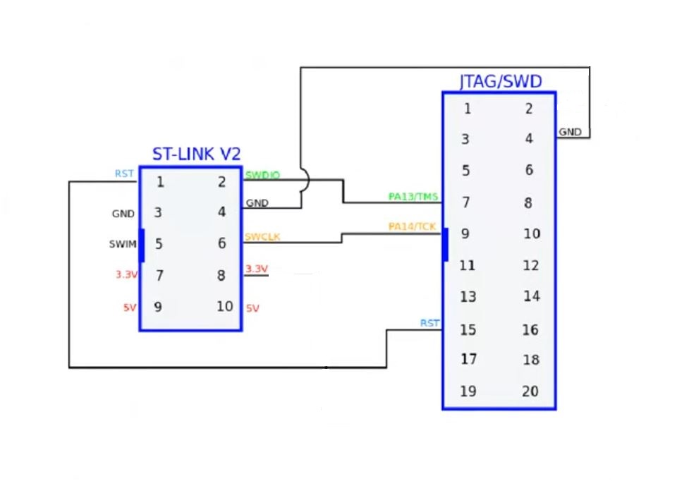
- JTAG/SWD: For programming and debugging the STM32F407VET6, connect to JTAG/SWD pins.
How to program:
- Micro Controller: STM32F407VET6 (32bit Arm Cortex M4 + FPU)
- Package Type: LQFP100
- Kernel: ARM Cortex-M4 with FPU
- Operating frequency: 168MHz
- Storage resources: 512K Byte Flash, 192KByte CCM SRAM
Interface Resources:
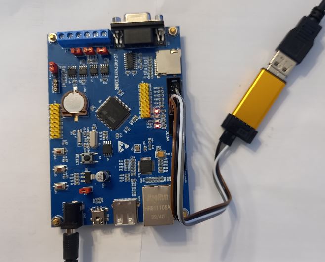
- SWD interface: JTAG / SWD/ JLink / STLink
- USB interface: Master USB / Slave USB
- USART1 interface: RS232 / RS485
- CAN: CAN1 / CAN2
- Temperature Sensor: DS18B20
- TF Card: Micro SD
- Ethernet: 1 X Ethernet
Other Device Description:
- Ethernet Chip: DP83848-LQFP48
- Power LED (PWR): x 1
- User LEDs : x 3 ( on pins PE13/PE14/PE15)
- Osc: 25M Crystal & 32.768KHz Crystal (RTC)
- User Buttons: x 3 Push Buttons
- RF Comms: NRF24L01 interface
- Power Input: DC +5V Input & USB
Programming IDEs:
- STM32 Cube - Download Here
- Arduino IDE - Download
Articles:
https://github.com/art103/JZ-F407VET6
Programming with Arduino IDE Using STLink V2:
1. Download and install Arduino IDE 2.2.1 on your PC (Latest Version).
2. Install support package:
File -> Preference => additional Board Manager URLs:
Enter the following url and click OK.
"https://github.com/stm32duino/BoardManagerFiles/raw/main/package_stmicroelectronics_index.json"
From Tools -> Manage Libraries
Search for STM32 and install the package:
"STM32 MCU based boards by STMicroelkectronics"
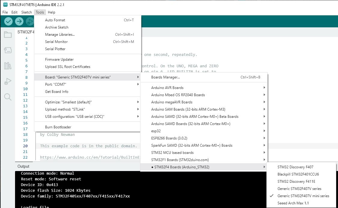
3. Select the Board:
Tools -> Bord -> STM32F4 Boards(Arduino_STM32) -> Generic STM32F407V mini series

Upload Method: STLink

A sample application with STM32F407VET6:
To use an STM32F407VET6 Cortex-M4 development board for industrial control applications, including interfacing with RS232, RS485, Dual CAN, Ethernet, and USB Host, you'll need to set up the board and write code to handle these peripherals. Here's a detailed guide to help you get started:
1. Hardware Connections
Pin Specification:
-
RS232:
- TX: Transmit pin of the RS232 interface (connect to RX of the external device).
- RX: Receive pin of the RS232 interface (connect to TX of the external device).
- GND: Ground pin (connect to the ground of the external device).
-
RS485:
- A: RS485 A pin (also known as the positive or non-inverted pin).
- B: RS485 B pin (also known as the negative or inverted pin).
- GND: Ground pin (connect to the ground of the external device).
-
CAN:
- CAN_H: CAN High pin (connect to the CAN High pin of the external device).
- CAN_L: CAN Low pin (connect to the CAN Low pin of the external device).
- GND: Ground pin (connect to the ground of the external device).
-
Ethernet:
- TX+ / TX-: Ethernet Transmit pins.
- RX+ / RX-: Ethernet Receive pins.
- GND: Ground pin.
-
USB Host:
- VBUS: USB power supply pin.
- D+: USB Data Positive pin.
- D-: USB Data Negative pin.
- GND: Ground pin.
2. Sample Code Using STM32 HAL Library:
First, make sure you have STM32CubeMX and STM32CubeIDE installed to configure peripherals and generate initialization code. Here's a basic example of how to set up and use RS232, RS485, CAN, and Ethernet with STM32 HAL.
#include "stm32f4xx_hal.h"
#include "stm32f4xx_hal.h"
#include "usb_host.h"

// UART handles for RS232 and RS485
UART_HandleTypeDef huart1; // RS232
UART_HandleTypeDef huart2; // RS485

// CAN handles
CAN_HandleTypeDef hcan1;
CAN_HandleTypeDef hcan2;

// Ethernet handle
ETH_HandleTypeDef heth;

// USB handle
USBH_HandleTypeDef hUsbHost;

// Function prototypes
void SystemClock_Config(void);
static void MX_GPIO_Init(void);
static void MX_USART1_UART_Init(void);
static void MX_USART2_UART_Init(void);
static void MX_CAN1_Init(void);
static void MX_CAN2_Init(void);
static void MX_ETH_Init(void);
static void MX_USB_HOST_Init(void);

int main(void)
{
  // Initialize the HAL Library
  HAL_Init();

  // Configure the system clock
  SystemClock_Config();

  // Initialize all configured peripherals
  MX_GPIO_Init();
  MX_USART1_UART_Init(); // RS232
  MX_USART2_UART_Init(); // RS485
  MX_CAN1_Init();
  MX_CAN2_Init();
  MX_ETH_Init();
  MX_USB_HOST_Init();

  // Example data
  uint8_t rs232_msg[] = "Hello via RS232!";
  uint8_t rs485_msg[] = "Hello via RS485!";
  CAN_TxHeaderTypeDef txHeader;
  uint8_t can_data[8] = {0x01, 0x02, 0x03, 0x04, 0x05, 0x06, 0x07, 0x08};
  uint32_t txMailbox;

  // CAN1 configuration
  txHeader.DLC = 8;
  txHeader.IDE = CAN_ID_STD;
  txHeader.RTR = CAN_RTR_DATA;
  txHeader.StdId = 0x123;

  // CAN2 configuration
  CAN_TxHeaderTypeDef txHeader2;
  uint8_t can_data2[8] = {0x11, 0x22, 0x33, 0x44, 0x55, 0x66, 0x77, 0x88};
  uint32_t txMailbox2;

  txHeader2.DLC = 8;
  txHeader2.IDE = CAN_ID_STD;
  txHeader2.RTR = CAN_RTR_DATA;
  txHeader2.StdId = 0x456;

  // Main loop
  while (1)
  {
    // Send a message via RS232
    HAL_UART_Transmit(&huart1, rs232_msg, sizeof(rs232_msg), HAL_MAX_DELAY);

    // Send a message via RS485
    HAL_UART_Transmit(&huart2, rs485_msg, sizeof(rs485_msg), HAL_MAX_DELAY);

    // Send a CAN message via CAN1
    HAL_CAN_AddTxMessage(&hcan1, &txHeader, can_data, &txMailbox);

    // Send a CAN message via CAN2
    HAL_CAN_AddTxMessage(&hcan2, &txHeader2, can_data2, &txMailbox2);

    // Handle Ethernet and USB Host
    MX_ETH_Init(); // This should be handled in the loop for network processing
    USBH_Process(&hUsbHost); // Process USB Host events

    // Add a delay
    HAL_Delay(1000);
  }
}

// Peripheral initialization functions

static void MX_USART1_UART_Init(void)
{
  huart1.Instance = USART1;
  huart1.Init.BaudRate = 9600;
  huart1.Init.WordLength = UART_WORDLENGTH_8B;
  huart1.Init.StopBits = UART_STOPBITS_1;
  huart1.Init.Parity = UART_PARITY_NONE;
  huart1.Init.Mode = UART_MODE_TX_RX;
  huart1.Init.HwFlowCtl = UART_HWCONTROL_NONE;
  huart1.Init.OverSampling = UART_OVERSAMPLING_16;
  HAL_UART_Init(&huart1);
}

static void MX_USART2_UART_Init(void)
{
  huart2.Instance = USART2;
  huart2.Init.BaudRate = 9600;
  huart2.Init.WordLength = UART_WORDLENGTH_8B;
  huart2.Init.StopBits = UART_STOPBITS_1;
  huart2.Init.Parity = UART_PARITY_NONE;
  huart2.Init.Mode = UART_MODE_TX_RX;
  huart2.Init.HwFlowCtl = UART_HWCONTROL_NONE;
  huart2.Init.OverSampling = UART_OVERSAMPLING_16;
  HAL_UART_Init(&huart2);
}

static void MX_CAN1_Init(void)
{
  hcan1.Instance = CAN1;
  hcan1.Init.Prescaler = 16;
  hcan1.Init.Mode = CAN_MODE_NORMAL;
  hcan1.Init.SJW = CAN_SJW_1TQ;
  hcan1.Init.BS1 = CAN_BS1_6TQ;
  hcan1.Init.BS2 = CAN_BS2_5TQ;
  hcan1.Init.TTCM = DISABLE;
  hcan1.Init.ABOM = DISABLE;
  hcan1.Init.ABS = DISABLE;
  hcan1.Init.RFLM = DISABLE;
  hcan1.Init.TXFP = DISABLE;
  HAL_CAN_Init(&hcan1);
}

static void MX_CAN2_Init(void)
{
  hcan2.Instance = CAN2;
  hcan2.Init.Prescaler = 16;
  hcan2.Init.Mode = CAN_MODE_NORMAL;
  hcan2.Init.SJW = CAN_SJW_1TQ;
  hcan2.Init.BS1 = CAN_BS1_6TQ;
  hcan2.Init.BS2 = CAN_BS2_5TQ;
  hcan2.Init.TTCM = DISABLE;
  hcan2.Init.ABOM = DISABLE;
  hcan2.Init.ABS = DISABLE;
  hcan2.Init.RFLM = DISABLE;
  hcan2.Init.TXFP = DISABLE;
  HAL_CAN_Init(&hcan2);
}

static void MX_ETH_Init(void)
{
  heth.Instance = ETH;
  heth.Init.AutoNegotiation = ETH_AUTONEGOTIATION_ENABLE;
  heth.Init.PhyAddress = 0;
  heth.Init.MACAddr = (uint8_t*)"\x00\x11\x22\x33\x44\x55";
  heth.Init.MediaInterface = ETH_MEDIA_INTERFACE_MII;
  heth.Init.RxMode = ETH_RXINTERRUPT_MODE;
  heth.Init.ChecksumMode = ETH_CHECKSUM_BY_HARDWARE;
  heth.Init.PTPMode = ETH_PTP_DISABLE;
  HAL_ETH_Init(&heth);
}

static void MX_USB_HOST_Init(void)
{
  USBH_Init(&hUsbHost, USBH_UserProcess, 0);
  USBH_RegisterClass(&hUsbHost, USBH_MSC_CLASS);
  USBH_Start(&hUsbHost);
}

void SystemClock_Config(void)
{
  RCC_ClkInitTypeDef clkinitstruct = {0};
  RCC_OscInitTypeDef oscinitstruct = {0};

  // Configure the main internal regulator output voltage
  __HAL_RCC_PWR_CLK_ENABLE();
  __HAL_PWR_VOLTAGESCALING_CONFIG(PWR_REGULATOR_VOLTAGE_SCALE1);

  // Initialize the CPU, AHB and APB busses clocks
  oscinitstruct.OscillatorType = RCC_OSCILLATORTYPE_HSE;
  oscinitstruct.HSEState = RCC_HSE_ON;
  oscinitstruct.HSIState = RCC_HSI_OFF;
  oscinitstruct.PLL.PLLState = RCC_PLL_ON;
  oscinitstruct.PLL.PLLSource = RCC_PLLSOURCE_HSE;
  oscinitstruct.PLL.PLLM = 8;
  oscinitstruct.PLL.PLLN = 336;
  oscinitstruct.PLL.PLLP = RCC_PLLP_DIV4;
  oscinitstruct.PLL.PLLQ = 7;
  HAL_RCC_OscConfig(&oscinitstruct);

  // Initialize the CPU, AHB and APB busses clocks
  clkinitstruct.ClockType = RCC_CLOCKTYPE_SYSCLK | RCC_CLOCKTYPE_HCLK | RCC_CLOCKTYPE_PCLK1 | RCC_CLOCKTYPE_PCLK2;
  clkinitstruct.SYSCLKSource = RCC_SYSCLKSOURCE_PLLCLK;
  clkinitstruct.AHBCLKDivider = RCC_HCLK_DIV1;
  clkinitstruct.APB1CLKDivider = RCC_APB1_DIV4;
  clkinitstruct.APB2CLKDivider = RCC_APB2_DIV2;
  HAL_RCC_ClockConfig(&clkinitstruct, FLASH_LATENCY_5);
}

static void MX_GPIO_Init(void)
{
  GPIO_InitTypeDef GPIO_InitStruct = {0};

  // Enable GPIO Ports Clock
  __HAL_RCC_GPIOA_CLK_ENABLE();
  __HAL_RCC_GPIOB_CLK_ENABLE();
  __HAL_RCC_GPIOC_CLK_ENABLE();
  __HAL_RCC_GPIOD_CLK_ENABLE();
  __HAL_RCC_GPIOE_CLK_ENABLE();

  // Configure GPIO pin Output Level
  HAL_GPIO_WritePin(GPIOA, GPIO_PIN_5, GPIO_PIN_RESET);

  // Configure GPIO pin : PA5
  GPIO_InitStruct.Pin = GPIO_PIN_5;
  GPIO_InitStruct.Mode = GPIO_MODE_OUTPUT_PP;
  GPIO_InitStruct.Pull = GPIO_NOPULL;
  GPIO_InitStruct.Speed = GPIO_SPEED_FREQ_LOW;
  HAL_GPIO_Init(GPIOA, &GPIO_InitStruct);
}

void USBH_UserProcess(USBH_HandleTypeDef *phost, uint8_t id)
{
  // USB Host user process callback
  switch(id)
  {
    case HOST_USER_SELECT_CONFIGURATION:
      break;
    case HOST_USER_DISCONNECTION:
      break;
    case HOST_USER_CLASS_ACTIVE:
      break;
    case HOST_USER_CONNECTION:
      break;
    default:
      break;
  }
}
3. Explanation of Code
-
Initialization Functions:
MX_USART1_UART_Init(): Configures UART1 for RS232 communication.MX_USART2_UART_Init(): Configures UART2 for RS485 communication.MX_CAN1_Init()andMX_CAN2_Init(): Initialize CAN1 and CAN2 interfaces for CAN communication.MX_ETH_Init(): Placeholder for Ethernet initialization.MX_USB_HOST_Init(): Placeholder for USB Host initialization.MX_GPIO_Init(): Initializes GPIO pins if necessary.
-
Main Loop:
- RS232: Sends a message via UART1 (RS232).
- RS485: Sends a message via UART2 (RS485).
- CAN1: Sends a CAN message using CAN1.
- CAN2: Sends a CAN message using CAN2.
- Ethernet and USB: Placeholders where you can add code for Ethernet and USB Host operations.
-
Delays and Communication:
HAL_Delay(1000);: Adds a 1-second delay between iterations of the main loop.
-
SystemClock_ConfigFunction:- Configures the system clock to use the PLL with HSE as the source.
- Sets the clock for the CPU, AHB, and APB busses.
- Adjust clock settings based on your specific application requirements.
-
MX_GPIO_InitFunction:- Initializes GPIO ports and sets up specific pins as output.
- In this example, only one pin (PA5) is configured as an output. Add additional pin configurations based on your needs.
-
MX_ETH_InitFunction:- Configures the Ethernet peripheral.
- Sets auto-negotiation, MAC address, and other parameters.
-
MX_USB_HOST_InitFunction:- Initializes the USB Host library and starts USB Host operations.
- Registers the MSC class for handling USB Mass Storage devices.
-
USB Host Callback:
USBH_UserProcesshandles USB Host events. You can add custom logic based on USB events (e.g., device connection/disconnection).
-
Main Loop:
- Regularly sends data via UART, CAN, and handles Ethernet and USB operations.
Make sure to adapt the configuration values and initialization code to match your specific hardware and requirements. Also, ensure that the STM32CubeMX tool is correctly configured for your project and that you have generated the necessary initialization code.
4. Development Environment
- STM32CubeMX: Use this tool to configure peripherals and generate initialization code.
- STM32CubeIDE: Integrated development environment for writing, compiling, and debugging code.
5. Additional Notes
- STM32CubeMX: Use STM32CubeMX to configure peripherals and generate initialization code. This tool will also help you configure the clock, GPIO pins, and peripheral settings.
- Power Supply: Ensure that your development board is powered correctly, as peripherals like CAN and Ethernet might require stable power sources.
- Debugging: Use STM32CubeIDE's debugging features to monitor and troubleshoot your code and hardware.
Request Stock
Recently viewed products
You might also be interested in...
Customers who bought this also bought...
General Questions
-
What is the latest price of the Industrial Control STM32F407VET6 Cortex M4 Development Board RS232 RS485 Dual CAN Ethernet USB Host in Bangladesh?
The latest price of Industrial Control STM32F407VET6 Cortex M4 Development Board RS232 RS485 Dual CAN Ethernet USB Host in Bangladesh is BDT 4,880.00 . You can buy the Industrial Control STM32F407VET6 Cortex M4 Development Board RS232 RS485 Dual CAN Ethernet USB Host at the best price on BDTronics.com or contact us via phone.
-
Where to buy Industrial Control STM32F407VET6 Cortex M4 Development Board RS232 RS485 Dual CAN Ethernet USB Host in Bangladesh?
You can buy Industrial Control STM32F407VET6 Cortex M4 Development Board RS232 RS485 Dual CAN Ethernet USB Host online by ordering on BDTronics.com or directly collect by visiting our store in person. BDTronics is a trusted provider of high-quality electronics, 3D printers, solar systems, and robotics parts. We offer fast shipping across the country via courier service.
-
What are the delivery options of Industrial Control STM32F407VET6 Cortex M4 Development Board RS232 RS485 Dual CAN Ethernet USB Host in Bangladesh?
We provide home delivery service all over Bangladesh. We support Cash on Delivery, Online Bank Transfer, bKash and Credit Card (Visa/ MasterCard/ Amex) payment solutions. The delivery time usually takes 1-2 days inside Dhaka and 2-4 days outside Dhaka.


